

Selecting the correct Split Core Current Transformer is critical for successful retrofit projects. Escalating emphasis on energy efficiency drives the need for advanced monitoring solutions. A technician first measures a conductor’s outer diameter. They also determine the maximum amperage the conductor will carry. Next, these physical and electrical needs are matched to a Split Core Current Sensor with the proper specifications. This includes the correct window size, current rating, accuracy class, and output signal. The chosen Split Core Current Transducer must be compatible with the existing power meter.
The split-core design allows for simple installation around existing conductors. This makes it ideal for retrofitting systems without interrupting current flow.
Key Takeaways
- Measure the conductor’s size and the maximum current. This ensures the CT fits and handles the electrical load safely.
- Match the CT’s output signal to your power meter. This prevents wrong data or damage to your equipment.
- Choose the right accuracy class for your needs. Billing requires high accuracy, while monitoring can use lower accuracy.
- Check for safety certifications like UL or CE marks. This confirms the CT meets safety standards.
- Consider the installation environment. This includes temperature, moisture, and corrosive elements for long-lasting use.
Sizing the CT: Conductor Diameter and Amperage Rating
Properly sizing a current transformer (CT) involves two fundamental steps. First, a technician must confirm the physical dimensions. Second, they must verify the electrical ratings. These initial measurements ensure the selected device fits correctly and performs accurately.
Measuring Conductor Diameter for Window Size
The first step in selecting a Split Core Current Transformer is a physical measurement. The technician must ensure the device’s opening, or “window,” is large enough to close around the conductor. An accurate measurement of the conductor’s outer diameter, including its insulation, is essential.
Technicians use several tools for this task. The choice of tool often depends on budget and the need for non-conductive safety.
- Plastic calipers offer a cost-effective and safe, non-conductive option for live environments.
- Digital micrometers provide high-precision measurements.
- Specialized tools like the Burndy Wire Mike are designed specifically for this application.
- Go/no-go gauges can also quickly verify if a conductor fits a predetermined size.
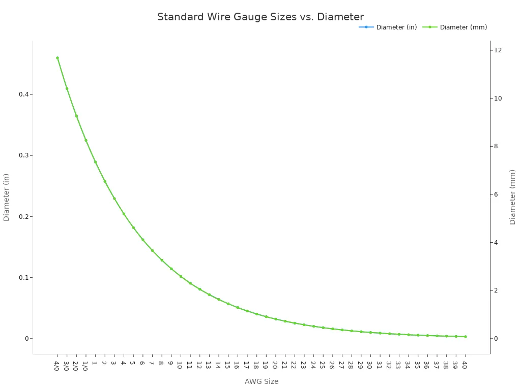
Conductor sizes in North America typically follow the American Wire Gauge (AWG) system. This standard, specified in ASTM B 258, defines the diameter of electrical wires. A smaller AWG number indicates a larger wire diameter. The following chart and table show the relationship between AWG size and diameter.
| AWG | Diameter (in) | Diameter (mm) |
|---|---|---|
| 4/0 | 0.4600 | 11.684 |
| 2/0 | 0.3648 | 9.266 |
| 1/0 | 0.3249 | 8.252 |
| 2 | 0.2576 | 6.543 |
| 4 | 0.2043 | 5.189 |
| 6 | 0.1620 | 4.115 |
| 8 | 0.1285 | 3.264 |
| 10 | 0.1019 | 2.588 |
| 12 | 0.0808 | 2.053 |
| 14 | 0.0641 | 1.628 |
Installations with multiple conductors bundled together require special attention. The CT window must be large enough to encircle the entire bundle. The combined circumference of the bundled wires dictates the minimum required window size.
Pro Tip: The CT window should fit luxuriously around the cable or busbar. A snug fit can make installation difficult, while an excessively oversized aperture can introduce measurement errors. The goal is a comfortable fit without significant empty space.
Determining the Maximum Current Rating
After confirming the physical fit, the next step is to select the correct amperage rating. The CT’s primary current rating must be greater than the maximum expected current of the monitored circuit. This rating is not the circuit breaker’s trip rating but the highest sustained amperage the load will draw.
A technician should account for potential future increases in electrical load. This practice prevents the need for a costly replacement later.
A common industry best practice is to select a CT with a primary rating that is 125% of the maximum continuous load. This 25% buffer provides a safety margin for future expansion and prevents the CT from saturating.
For example, if a circuit’s maximum continuous load is 80A, a technician would calculate the minimum CT rating as 80A * 1.25 = 100A. In this case, a 100A Split Core Current Transformer would be the appropriate choice. Undersizing a CT can lead to core saturation, resulting in inaccurate readings and potential damage. Conversely, significant oversizing can reduce accuracy at lower current levels, so finding the right balance is key.
Matching the Output Signal to Your Meter
Once a technician confirms the physical sizing, the next critical task is to ensure electrical compatibility. A Split Core Current Transformer acts as a sensor, converting high primary current into a low-level signal. This output signal must precisely match what the power meter or monitoring device is designed to accept. An incorrect match will lead to faulty data or, in some cases, damage to the equipment.
Understanding Common CT Outputs (5A, 1A, 333mV)
Current transformers are available with several standard output signals. The three most common types found in retrofit applications are 5 Amp (5A), 1 Amp (1A), and 333 millivolt (333mV). Each has distinct characteristics and is suited for different scenarios.
5A and 1A Outputs: These are traditional current outputs. The CT produces a secondary current that is directly proportional to the primary current. For example, a 100:5A CT will produce 5A on its secondary when 100A flows through the primary conductor. While 5A has been the historical standard, 1A outputs are gaining popularity for new installations.
⚠️ Critical Safety Warning: A CT with a 5A or 1A output is a current source. Its secondary circuit must never be left open while the primary conductor is energized. An open secondary can generate extremely high, dangerous voltages (often thousands of volts), posing a severe shock hazard. This condition can also cause the CT’s core to overheat and fail, potentially destroying the CT and damaging connected devices. Always ensure the secondary terminals are shorted or connected to a meter before energizing the primary circuit.
The choice between a 1A and 5A output often depends on the distance to the meter and project specifications.
| Feature | 1A Secondary CT | 5A Secondary CT |
|---|---|---|
| Power Loss | Lower power loss (I²R) in lead wires. | Higher power loss in lead wires. |
| Lead Length | Better for long distances due to lower voltage drop and burden. | Limited to shorter distances to maintain accuracy. |
| Wire Size | Allows for smaller, less expensive lead wires. | Requires larger, more expensive lead wires for long runs. |
| Safety | Lower induced voltage if the secondary is accidentally opened. | Higher induced voltage and greater risk if opened. |
| Cost | Generally more expensive due to more secondary windings. | Typically less expensive. |
| Compatibility | Growing standard, but may require newer meters. | Traditional standard with broad compatibility. |
333mV Output: This type of CT produces a low-level voltage signal. These CTs are inherently safer because they have a built-in burden resistor that converts the secondary current to a voltage. This design prevents the high-voltage hazard associated with open-circuiting a 1A or 5A CT. The 333mV signal is a common standard for modern digital power meters.
Another sensor type, the Rogowski Coil, also produces a millivolt-level output. However, it requires a separate integrator to function correctly. Rogowski coils are flexible and ideal for measuring very high currents or in applications with wide frequency ranges, but they are generally not suitable for loads under 20A.
Verifying Your Meter’s Input Requirements
The most fundamental rule of CT selection is that the CT’s output must match the meter’s input. A meter designed for a 333mV input cannot read a 5A signal, and vice versa. This verification process involves checking datasheets and understanding the concept of burden.
First, a technician must identify the input type specified by the meter manufacturer. This information is usually printed on the device label or detailed in its installation manual. The input will be clearly stated as 5A, 1A, 333mV, or another specific value.
Second, a technician must consider the total burden on the CT. Burden is the total load connected to the CT’s secondary, measured in Volt-Amps (VA) or Ohms (Ω). This load includes:
- The internal impedance of the meter itself.
- The resistance of the lead wires running from the CT to the meter.
- The impedance of any other connected devices.
Every CT has a maximum burden rating (e.g., 1VA, 2.5VA, 5VA). Exceeding this rating will cause the CT to lose accuracy. As the table below shows, the input impedance of a meter varies drastically by type, which is a major component of the total burden.
| Meter Input Type | Typical Input Impedance |
|---|---|
| 5A Input | < 0.1 Ω |
| 333mV Input | > 800 kΩ |
| Rogowski Coil Input | > 600 kΩ |
The low impedance of a 5A meter is designed to be a near-short circuit, while the high impedance of a 333mV meter is designed to measure voltage without drawing significant current.
Pro Tip: Always consult the manufacturer’s documentation for both the CT and the meter. Many manufacturers provide compatibility tables that explicitly list which CT models are approved for use with specific meters or inverters. Cross-referencing these documents is the surest way to guarantee a successful installation.
For example, an inverter manufacturer might provide a chart showing that its “Model X” hybrid inverter is only compatible with the “Eastron SDM120CTM” meter and its associated CT. Attempting to use a different CT, even with the correct output signal, could void warranties or lead to system malfunction.
Choosing the Right Accuracy Class for Your Application
After sizing the CT and matching its output, a technician must select the appropriate accuracy class. This rating defines how closely the CT’s secondary output represents the actual primary current. Choosing the correct class ensures the collected data is reliable enough for its intended purpose, whether for critical billing or general monitoring. An improper selection can lead to financial discrepancies or flawed operational decisions.
Defining CT Accuracy Classes
International standards, such as IEC 61869-2, define CT accuracy classes. This standard specifies the allowable error at different percentages of the CT’s rated current. A key distinction exists between standard classes and special, more rigorous classes.
- The IEC 61869-2 standard outlines performance requirements for both current ratio error and phase displacement.
- Special ‘S’ class CTs (e.g., Class 0.5S) have stricter error limits at low current levels compared to their standard counterparts (e.g., Class 0.5).
- For example, at 5% of the rated current, a Class 0.5 CT can have a 1.5% error, while a Class 0.5S CT must be within 0.75%.
Accuracy involves more than just the current magnitude. It also includes phase displacement, or phase error. This is the time delay between the primary current waveform and the secondary output waveform. Even a small phase error can impact power calculations.
When to Choose Billing-Grade vs. Monitoring-Grade Accuracy
The application dictates the required accuracy. CTs generally fall into two categories: billing-grade and monitoring-grade.
Billing-grade CTs (e.g., Class 0.5, 0.5S, 0.2) are essential for revenue applications. When a utility company or landlord bills a tenant for energy usage, the measurement must be highly accurate. A small phase error can cause significant inaccuracies in active power measurement, especially in systems with a low power factor. This directly translates to incorrect financial charges.
Inaccurate power measurements from phase error can also cause problems beyond billing. In three-phase systems, it can lead to unbalanced loads and equipment stress. It may even cause protective relays to malfunction, creating safety risks.
Monitoring-grade CTs (e.g., Class 1.0 and above) are suitable for general energy management. Technicians use them for tracking equipment performance, identifying load patterns, or allocating costs internally. For these tasks, a slightly lower degree of precision is acceptable. Selecting the right Split Core Current Transformer ensures the data’s integrity matches the project’s financial and operational stakes.
Verifying Your Split Core Current Transformer for Safety and Environment
A technician’s final checks involve confirming safety certifications and assessing the installation environment. These steps ensure the selected Split Core Current Transformer operates reliably and safely for its entire service life. Neglecting these verifications can lead to premature failure, safety hazards, and non-compliance with regional regulations.
Checking for UL, CE, and Other Certifications
Safety certifications are non-negotiable. They confirm that a product has been tested by an independent body to meet specific safety and performance standards. In North America, a technician should look for a UL or ETL mark. In Europe, the CE mark is mandatory.
The CE mark indicates compliance with European Union directives, such as the Low Voltage Directive. To apply this mark, a manufacturer must:
- Conduct a thorough risk assessment to identify and mitigate potential hazards.
- Perform conformity tests according to harmonized standards.
- Issue a formal Declaration of Conformity, a legal document assuming responsibility for the product’s compliance.
- Maintain technical documentation, including risk analysis and operating instructions.
Always verify that the certifications are genuine and apply to the specific model being purchased. This due diligence protects both the equipment and personnel.
Assessing the Installation Environment
The physical environment significantly impacts a CT’s longevity and accuracy. A technician must evaluate three key factors: temperature, moisture, and contaminants.
Operating Temperature: Every CT has a specified operating temperature range. Some models operate from -30°C to 55°C, while others, like certain Hall Effect sensors, can handle -40°C to +85°C. A technician must choose a device rated for the ambient temperatures of the installation site, from the coldest winter night to the hottest summer day.
Moisture and Ingress Protection (IP): High humidity and direct water exposure are major threats. Moisture can degrade insulation, corrode metal components, and lead to electrical faults. The Ingress Protection (IP) rating indicates a device’s resistance to dust and water.
| IP Rating | Dust Protection | Water Protection |
|---|---|---|
| IP65 | Dust tight | Protected from low-pressure water jets |
| IP67 | Dust tight | Protected from immersion up to 1m |
| IP69K | Dust tight | Protected from steam-jet cleaning |
An IP65 rating is often sufficient for general-purpose enclosures. However, outdoor installations may require IP67 for protection against immersion. For harsh wash-down environments, such as in food processing, an IP69K-rated Split Core Current Transformer is essential.
Corrosive Atmospheres: Locations near coastlines or industrial plants may have salt or chemicals in the air. These corrosive agents accelerate the degradation of a CT’s housing and internal components. In such environments, a technician should select a CT with robust, corrosion-resistant materials and sealed enclosures.
A technician ensures a successful retrofit by following a final checklist. This confirms the Split Core Current Transformer meets all project needs.
- Window Size: Fits the conductor diameter.
- Amperage: Exceeds the maximum circuit load.
- Output Signal: Matches the meter’s input.
- Accuracy Class: Suits the application (billing vs. monitoring).
A technician must always verify the selected Split Core Current Transformer is fully compatible with the metering hardware. Prioritizing models with proper safety certifications for the region protects both personnel and equipment.
FAQ
What happens if a technician installs a CT backward?
A technician installing a CT backward reverses the current flow’s polarity. This causes the meter to show negative power readings. For correct measurements, the arrow or label on the CT housing must point in the direction of the current flow, toward the load.
Can a technician use one large CT for multiple conductors?
Yes, a technician can pass multiple conductors through a single CT. The CT will measure the net (vector sum) of the currents. This method works for monitoring total power. It is not suitable for measuring individual circuit consumption.
Why is my 333mV CT reading incorrectly?
Incorrect readings often result from a mismatch between the CT and the meter. A technician must confirm the meter is configured for a 333mV input. Using a 333mV CT with a meter expecting a 5A input will produce inaccurate data.
Does a current transformer need its own power source?
No, a standard passive CT does not require an external power source. It harvests energy directly from the magnetic field of the conductor it measures. This simplifies installation and reduces wiring complexity. Active sensors, like some Hall Effect devices, may need auxiliary power.
Post time: Nov-11-2025